
Intro to STM32 Lesson 4: ADC/DMA

Intro to STM32 Lesson 4: ADC/DMA Time Required: 30 Minutes This tutorial introduces the analog-to-digital converter (ADC) as well as the direct memory access (DMA) controller. While these two hardware peripherals don’t necessarily need to be used together they certainly can help each other! Prerequisites Before Starting Everything from Lessons 1 through 3 STM32 MCU of your choice with USB cable ADC MCUs are digital components and, as a result, can only process digital signals from GPIO pins. Of course, there are an infinite number of voltage levels between LOW (0V) and HIGH (3V3, 5V, etc.). Many types of signals such as audio are entirely analog. To capture these types of signals we use an ADC which samples the signal at a specified sampling rate. By taking a measurement at each sample time, we are able to approximate the analog signal digitally: (Source: Tony R. Kuphaldt – Lessons in Electric Circuits) As can be seen in the example above, a few samples will begin to approximate the signal but won’t entirely recreate it. When this loss of accuracy occurs during sampling it is called aliasing. In order to prevent aliasing we must sample at the Nyquist Frequency which is twice the maximum frequency within the signal. Each ADC has a resolution, typically 10-bit or 12-bit: (Source: Arrow Research) As the ADC resolution increases, so does the resolution of the sampled digital signal: (Source: Apple Inc – Soundtrack Pro 3: Audio Fundamentals) There are two types of ADC implementations used with STM32 chips, each with advantages and disadvantages: Successive-Approximation Register (SAR) Faster, less resolution Sigma-Delta Modulation Slower, more resolution For the purposes of this tutorial we will be using a NUCLEO-144 with STM32F756ZG MCU. From the ST website we can tell that it is equipped with 3 x 12-bit ADCs. DMA One of the biggest challenges with processing ADC data is the sheer amount of it. MCUs are relatively lightweight processors with limited memory and processing capabilities. If the CPU is occupied moving an ADC reading from the hardware buffer into memory it cannot be performing a calculation on the data at the same time. Every byte that needs to pass through the CPU slows it down, this is where DMA can make a world of difference. Most modern processors have a hardware DMA controller. There is a small amount of CPU time required to configure the peripheral, but in cases of large data transfers this initial cost is almost always eclipsed by the total time saved. DMA can be imagined as a temporary information highway that can be placed between two destinations in the MCU, such as the ADC and Memory. Consider an example where we need to collect significant amounts of data from an ADC and store it in a Memory buffer. Without DMA, every time the ADC raises an interrupt to signal it has data ready to read the CPU needs to stop what it’s doing, read the data into a CPU register, then write it to the Memory buffer before it can resume what it was doing before. In this case the CPU becomes the bottleneck, restricting the system from operating at it’s maximum throughput due to constant context changes. Adding a DMA pipeline transforms the system from this: (Source: Digikey) To this, effectively removing the CPU bottleneck: (Source: Digikey) Reading From the ADC Let’s start with a simple ADC conversion, confirm everything is working properly, then add DMA. Configure USART3 as Asynchronous with PD9 as USART3_RX and PD8 as USART3_TX in the GUI: Note: Different pins will likely need to be selected for non-STM32F756ZG boards. Enable IN0 for ADC1 and set PA0 as ADC1_IN0 : Note: Different pins will likely need to be selected for non-STM32F756ZG boards. Add the following changes to main.c : /* USER CODE BEGIN Header */ /** ****************************************************************************** * @file : main.c * @brief : Main program body ****************************************************************************** * @attention * * Copyright (c) 2024 STMicroelectronics. * All rights reserved. * * This software is licensed under terms that can be found in the LICENSE file * in the root directory of this software component. * If no LICENSE file comes with this software, it is provided AS-IS. * ****************************************************************************** */ /* USER CODE END Header */ /* Includes ——————————————————————*/ #include “main.h” /* Private includes ———————————————————-*/ /* USER CODE BEGIN Includes */ #include <string.h> #include <stdio.h> /* USER CODE END Includes */ /* Private typedef ———————————————————–*/ /* USER CODE BEGIN PTD */ /* USER CODE END PTD */ /* Private define ————————————————————*/ /* USER CODE BEGIN PD */ /* USER CODE END PD */ /* Private macro ————————————————————-*/ /* USER CODE BEGIN PM */ /* USER CODE END PM */ /* Private variables ———————————————————*/ ADC_HandleTypeDef hadc1; UART_HandleTypeDef huart3; /* USER CODE BEGIN PV */ /* USER CODE END PV */ /* Private function prototypes ———————————————–*/ void SystemClock_Config(void); static void MX_GPIO_Init(void); static void MX_ADC1_Init(void); static void MX_USART3_UART_Init(void); /* USER CODE BEGIN PFP */ /* USER CODE END PFP */ /* Private user code ———————————————————*/ /* USER CODE BEGIN 0 */ /* USER CODE END 0 */ /** * @brief The application entry point. * @retval int */ int main(void) { /* USER CODE BEGIN 1 */ uint16_t buffer; char msg[4]; /* USER CODE END 1 */ /* MCU Configuration——————————————————–*/ /* Reset of all peripherals, Initializes the Flash interface and the Systick. */ HAL_Init(); /* USER CODE BEGIN Init */ /* USER CODE END Init */ /* Configure the system clock */ SystemClock_Config(); /* USER CODE BEGIN SysInit */ /* USER CODE END SysInit */ /* Initialize all configured peripherals */ MX_GPIO_Init(); MX_ADC1_Init(); MX_USART3_UART_Init(); /* USER CODE BEGIN 2 */ /* USER CODE END 2 */ /* Infinite loop */ /* USER CODE BEGIN WHILE */ while (1) { // Get ADC value HAL_ADC_Start(&hadc1); HAL_ADC_PollForConversion(&hadc1, HAL_MAX_DELAY); buffer = HAL_ADC_GetValue(&hadc1); // Convert to string and print sprintf(buffer, “%hurn”, buffer); HAL_UART_Transmit(&huart3, (uint8_t*)buffer, strlen(buffer), HAL_MAX_DELAY); // Delay HAL_Delay(1); /* USER CODE END WHILE */ /* USER CODE BEGIN 3 */ } /* USER CODE END
Intro to STM32 Lesson 3: USART

Intro to STM32 Lesson 3: USART Time Required: 20 Minutes ⏱️ This tutorial goes through the steps for establishing a RS232 serial connection with an STM32 MCU for receiving and sending text over the USART or UART (Universal Synchronous Asynchronous Receiver Transmitter). Serial communication is the process of sequentially sending data one bit at a time over a single wire. It is one of the most simple yet effective methods of connecting your MCU with sensors, other processors, or, in this case, your computer. Prerequisites Before Starting Everything from Lesson 2: GPIO STM32 Board Tutorial uses STM32F756ZG Nucleo 144 USB Cable Create a New Project with STM32XCubeMX Open STM32CubeMX Select New Project or Menu > File > New Project Under Board Selector select the series and type of your STM32 board, for this tutorial the NUCLEO-FZ576ZG STM32F7 Series Nucleo144 type will be used Select Start Project and Yes for initializing all peripherals with their default mode including the MPU Clock Configuration The default settings under Clock Configuration (see below) should be sufficient for the purpose of this application. Pinout Configuration STM32 Nucleo boards include an ST-LINK onboard USB programmer and debugger with a few extra features including a USART. Many of the STM32 Software Defaults do not match the STM32 hardware defaults. Using your STM32’s datasheet and User Guide will be key to determining the correct pinout. Open Pinout & Configuration > Connectivity in STM32CubeMX and select USART3 Under Mode select Asynchronous Take note of the settings under Basic Parameters at the bottom as we’ll need these for our terminal later Now we need to select the USART RX and TX pins, if you type USART3_RX into the search bar, you’ll see both PB11 and PD9 start blinking. Which one is the correct choice? The answer is… it depends. Most MCUs will have multiple pins connected to each USART so serial data can be read from multiple locations by the same on-board hardware. In this case, we want to connect USART3 to the on-board ST-LINK so that it can be connected to the computer. A quick search for USART3 points us to the following section in the Nucleo-144 User Manual. It can be seen from this table that PD9 is the correct selection for USART3 RX and PD8 is the correct selection for USART3 TX. Click on PD9 and select USART3_RX . Click on PD8 and select USART3_TX . Switch to the Project Manager tab, name the project, and select STM32CubeIDE as the Toolchain / IDE. Now generate your code! If you need help doing this check out Lesson 2: GPIO Code Configuration Open STM32CubeIDE Open <YOUR_PROJECT_NAME>/Src/main.c in Project Explorer Add the following snippet between /* USER CODE BEGIN 3 */ and /* USER CODE END 3 */ uint8_t Test[] = “STM32 USART Lesson Complete!rn”; // String to send over USART HAL_UART_Transmit(&huart3,Test,sizeof(Test),10); // Send in normal mode HAL_Delay(2000); // Wait 2 seconds before next transmit Open a serial console emulator of your choice such as PuTTY or TeraTerm. Ensure the baud rate and data bit length is the same as the settings selected above (1152000 Baud, 8 Bit Data). Select the COM Port the STM32 is connected to and open the connection. In STM32CubeIDE click Run to build and load the project onto the STM32 MCU STM32 USART Lesson Complete! should now be visible within your serial console Congratulations! You can now communicate with your STM32MCU! Next we’ll dive into reading analog values with an Analog Digital Converter (ADC) and how to speed up this process with a Direct Memory Access (DMA) Controller in Lesson 4: ADC & DMA
Intro to STM32 Lesson 2: GPIO
Intro to STM32 Lesson 2: GPIO Time Required: 30 Minutes This tutorial goes through the steps for blinking an LED using an STM32 MCU. The clock and GPIO configuration code will be generated for us by STM32CubeMX, STM32’s graphical code generation tool. We’ll then add the code to blink the STM32F756ZG Nucleo 144’s on-board LED in STM32CubeIDE to verify everything is working properly. The STM32 ecosystem is very powerful because it allows us to configure our project and MCU graphically through STM32CubeMX instead of textually directly through code. As you will see, most of this tutorial is setup in STM32CubeMX with only the specific behavior we want (blinking an LED) added at the end in STM32CubeIDE. If you’re interested in transitioning from Arduino to a more powerful MCU, you’ll absolutely find this to be one of the best options available today. Prerequisites Before Starting Everything from Lesson 1: Setup STM32 Board Tutorial uses STM32F756ZG Nucleo 144 USB Cable Create a New Project with STM32XCubeMX Open STM32CubeMX Select New Project or Menu > File > New Project Under Board Selector select the series and type of your STM32 board, for this tutorial the NUCLEO-FZ576ZG STM32F7 Series Nucleo144 type will be used Select Start Project and Yes for initializing all peripherals with their default mode including the MPU Clock Configuration The default settings under Clock Configuration (see below) should be sufficient for the purpose of this application. Pinout Configuration In Pinout > SYS Peripheral ensure that Serial Wire is selected as the debug interface. This will automatically configure PA13 as TMS and PA14 as TCK. In order to figure out which pins are connected to the red, green, and blue onboard LEDs we’ll need to take a look at the user guide for the STM32 Nucleo 144. A quick search for “LED” will lead us to the LEDs portion of the Hardware Layout and Configuration section. From this we can see: The Green LED is connected to Port B pin 0 or PB0 The Blue LED is connected to Port B pin 7 or PB7 The Red LED is connected to Port B pin 14 or PB14 Let’s try to blink the Blue LED. First we need to set the pin as a GPIO_Output by clicking on the pin in the viewer and selecting GPIO_Output. The pin should turn green with a thumbtack after. GPIO Configuration Select GPIO under System Core to bring up the following screen: PB7 should be displayed as above with the exception of the User Label. This can be added under PB7 Configuration at the bottom of the screen. With a User Label added it is now possible to search for the pin in the search bar in the bottom right hand corner of the screen. If you want the LED to start in the “off-state”, leave GPIO Output Level as low. If you want the LED to start in the “on-state”, change GPIO Output Level to High. Project Configuration and Source Code Generation Open the Project Manager tab to configure the project. Select your desired Project Name and Project Location if not using the default location: Select STM32CubeIDE as the Toolchain/IDE under Code Generator: Click on Code Generator and ensure the following options are selected: STM32Cube MCU packages and embedded software packs > Copy only the necessary library files Generated files > Keep User Code when re-generating Finally click on Generate Code followed by Open Project in the popup to open the project in STM32CubeIDE Source Code Configuration with HAL Now we need to add in the code changes that toggle the LED. To determine which functions to use, we need to look at the HAL User Manual for our STM32MCU. HAL or Hardware Abstraction Layer is the set of low level functions that we can use to control the STM32 MCU without needing to worry too much about what’s going on under the hood. The HAL User manual for the STM32F7 series is UM1905 and can be found here. Inside the user manual we’ll find HAL_GPIO_TogglePin which toggles a GPIO pin from LOW to HIGH or HIGH to LOW depending on the state when it’s called. In the Project Explorer sidebar open Src/main.c and navigate to the while(1) loop between the /* USER CODE BEGIN 3 */ and /* USER CODE END 3 */ section. Placing code in here will preserve it after regeneration with STM32CubeMX. Add the following snippet inside the loop to toggle the LED and delay for 0.5 seconds so we can see it blink: HAL_GPIO_TogglePin(GPIOB, GPIO_PIN_7); HAL_Delay(500) /* 500 ms delay */ Build and Debug the Project Ensure the CN1 connector if applicable on your board to allow the board to be powered over the USB connection To build the project, either click the Build button in the toolbar OR right click on the project in the project explorer side base and select Build Project To debug the project, click on the debug icon and OK in the Edit Configuration popup This should open the debugger. You can switch to the debugger view if desired but it’s not necessary. If you see Download verified successfully in the console your program has been successfully loaded onto the MCU! Click on the Resume button to continue program execution You should now see the Blue LED flashing. Congratulations! You are now able to: Graphically configure GPIO Pins with STM32CubeMX Add GPIO functionality in code with STM32CubeIDE Find and use HAL functions for cleaner and easier to write code Great job! For more check out Lesson 3: USART
Intro to STM32 Lesson 1: Setup
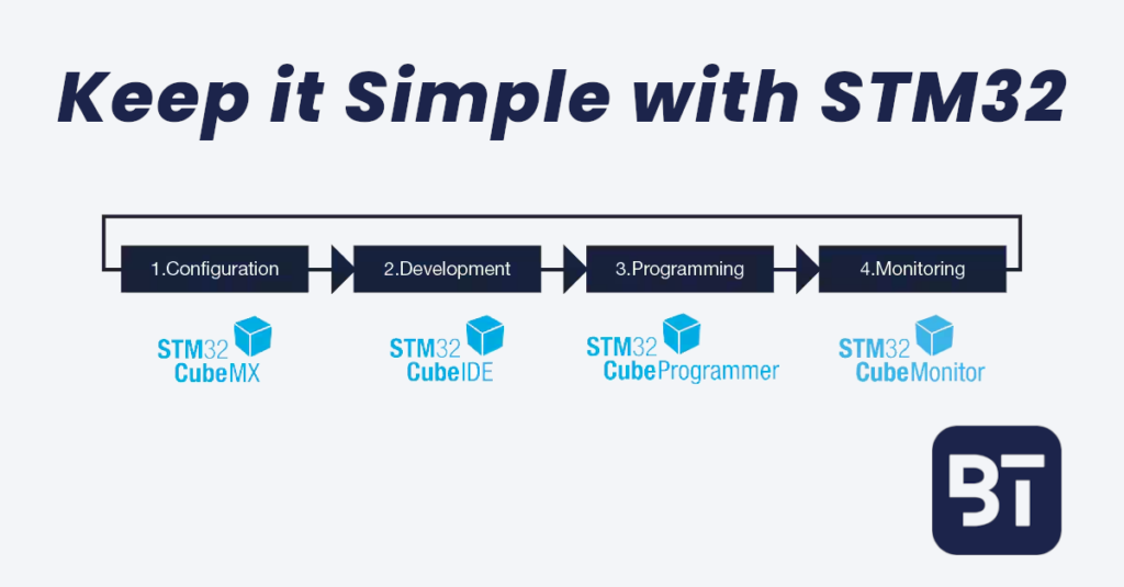
Intro to STM32 Lesson 1: Setup Time Required: 45 Minutes Prerequisites Before Starting Computer with Windows 7 or later, OSX, or Linux Java Internet Access STM32 Nucleo Board Any will do but the exact instructions and pins may change depending on your selection This course uses the STM32F756ZG Nucleo-144 USB Cable Micro, Mini, or USB-C depending on your STM32 board Required Tools STM32 has a few different required tools to get up and running. While it may seem like a lot of overhead at first, each tool serves a unique purpose in the STM32 ecosystem with the overall goal of successful STM32 development. STM32CubeMX graphically generates easy to understand and edit code. STM32CubeProgrammer communicates, programs, and debugs. STM32CubeIDE leverages the ecosystem so you can focus on building. STM32CubeMonitor records, analyzes, and plots data in real-time. Installing STM32CubeMX STM32CubeMX is used to graphically program and configure the STM32 by generating C code. This is really useful because you can see what’s going on “under the hood” and make precise changes as necessary. Something that’s (usually) not possible with Arduino. STM32CubeMX can be downloaded from the website here. Note: You will need to sign up for a STM32 account to download the software. Installing STM32CubeIDE STM32CubeIDE is the IDE or Integrated Development Environment that is used to develop STM32 software/firmware. It is possible to use a different IDE or text editor such as VSCode and generate the code with STM32CubeMX as well. That being said, even though I’m a very hardcore VSCode fan, I’ve found that STM32CubeIDE is the easiest program to use for STM32 development. STM32CubeIDE can be downloaded from the website here. Note: You will need to sign up for a STM32 account to download the software. Installing STM32CubeProg STM32CubeProg(rammer) is used to load/spy software in STM32. The software also includes the USB Driver and can be downloaded here. Note: You will need to sign up for a STM32 account to download the software. Installing STM32CubeMonitor STM32CubeMonitor is used to fine-tune applications at run time through data analysis and visualization. It also provides a flow based editor to quickly build custom dashboards with widgets such as plots and gauges. The software can be downloaded here. Note: You will need to sign up for a STM32 account to download the software. Installing The STM32CubeMX Firmware Package To start developing with your STM32 processor the firmware package must first be downloaded in STM32CubeMX. The firmware package needed will be STM32 followed by the first letter and number in your processor. For example, in this tutorial we will be using a Nucleo 144 Development Board with the STM32F756ZG so the firmware package would be STM32FG Open STM32CubeMX Click on Help > Manage embedded software packages or press <alt> + u Select the latest STM32Cube Firmware Package and click Install For the STM32F756ZG when this tutorial was written the latest version was STM32F7 Series 1.17 Run Your First STM32 Program Connect your STM32 device to your computer using the USB cable. In the case of the STM32F756ZG Nucleo 144 this is a micro USB cable but it may be a mini USB or USB-C depending on the configuration and processor capabilities Ensure the CN-1 and CN-2 jumpers are on and the ST-Link driver is installed properly Open STM32CubeIDE and select the default workspace. Click on File > Open Projects from File System Within the window, click Directory and select <YOUR_STM32CUBE_INSTALL_PATH>STM32CubeRepositorySTM32Cube_FW_<YOUR_STM32_PROCESSOR_SERIES>__Vx.xx.xProjectsNUCLEO-L476RGExamples_LLGPIOGPIO_InfiniteLedToggling This path will vary according to your STM32 processor Select GPIO_InfiniteLedTogglingSW4STM32STM32L476RG_NUCLEO and accept the popup asking to convert the project into an STM32CubeIDE project Now the project is under STM32CubeIDE and can be accessed Default STM32CubeIDE settings are fine Click the Debug icon to start debugging Ensure to click the “Shared ST-Link” option under Debug configurations > Debugger Click Resume to continue the program execution Congratulations! You are now able to: Generate code graphically with STM32CubeMX Debug an STM32 MCU with STM32CubeIDE Find and install STM32 libraries Control a GPIO pin to make an LED blink Great start! For more check out Lesson 2: GPIO