Intro to STM32 Lesson 2: GPIO
Time Required: 30 Minutes
This tutorial goes through the steps for blinking an LED using an STM32 MCU. The clock and GPIO configuration code will be generated for us by STM32CubeMX, STM32’s graphical code generation tool. We’ll then add the code to blink the STM32F756ZG Nucleo 144’s on-board LED in STM32CubeIDE to verify everything is working properly.
The STM32 ecosystem is very powerful because it allows us to configure our project and MCU graphically through STM32CubeMX instead of textually directly through code. As you will see, most of this tutorial is setup in STM32CubeMX with only the specific behavior we want (blinking an LED) added at the end in STM32CubeIDE. If you’re interested in transitioning from Arduino to a more powerful MCU, you’ll absolutely find this to be one of the best options available today.
Prerequisites Before Starting
- Everything from Lesson 1: Setup
- STM32 Board
- Tutorial uses STM32F756ZG Nucleo 144
- USB Cable
Create a New Project with STM32XCubeMX
-
- Open STM32CubeMX
- Select New Project or Menu > File > New Project
- Under Board Selector select the series and type of your STM32 board, for this tutorial the NUCLEO-FZ576ZG STM32F7 Series Nucleo144 type will be used
- Select Start Project and Yes for initializing all peripherals with their default mode including the MPU

Clock Configuration
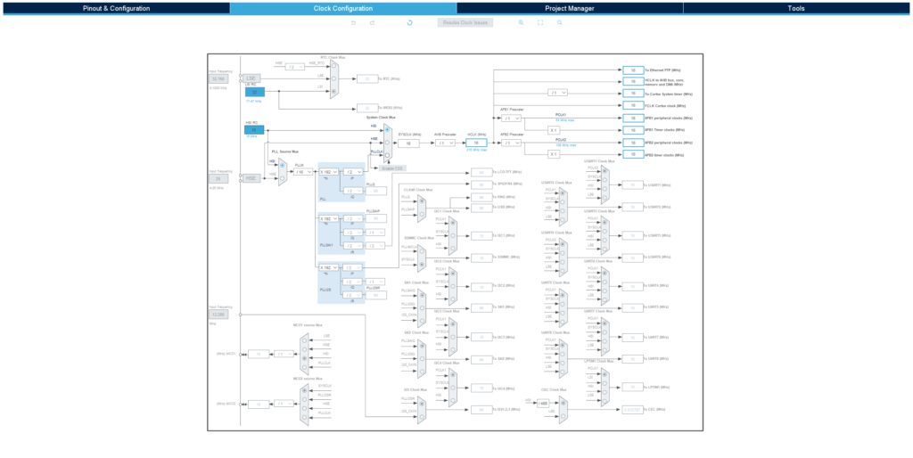
The default settings under Clock Configuration (see below) should be sufficient for the purpose of this application.

Pinout Configuration
In Pinout > SYS Peripheral ensure that Serial Wire is selected as the debug interface. This will automatically configure PA13 as TMS and PA14 as TCK.

In order to figure out which pins are connected to the red, green, and blue onboard LEDs we’ll need to take a look at the user guide for the STM32 Nucleo 144. A quick search for “LED” will lead us to the LEDs portion of the Hardware Layout and Configuration section.

From this we can see:
-
- The Green LED is connected to Port B pin 0 or PB0
-
- The Blue LED is connected to Port B pin 7 or PB7
-
- The Red LED is connected to Port B pin 14 or PB14
Let’s try to blink the Blue LED. First we need to set the pin as a GPIO_Output by clicking on the pin in the viewer and selecting GPIO_Output. The pin should turn green with a thumbtack after.


GPIO Configuration
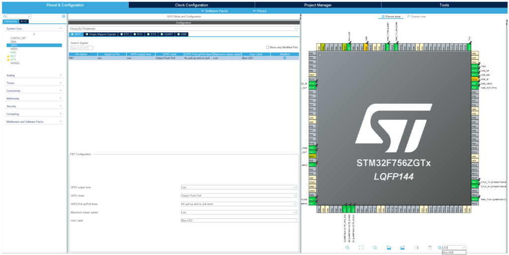
Select GPIO under System Core to bring up the following screen:

PB7 should be displayed as above with the exception of the User Label. This can be added under PB7 Configuration at the bottom of the screen. With a User Label added it is now possible to search for the pin in the search bar in the bottom right hand corner of the screen.
If you want the LED to start in the “off-state”, leave GPIO Output Level as low. If you want the LED to start in the “on-state”, change GPIO Output Level to High.
Project Configuration and Source Code Generation
Open the Project Manager tab to configure the project. Select your desired Project Name and Project Location if not using the default location:

Select STM32CubeIDE as the Toolchain/IDE under Code Generator:

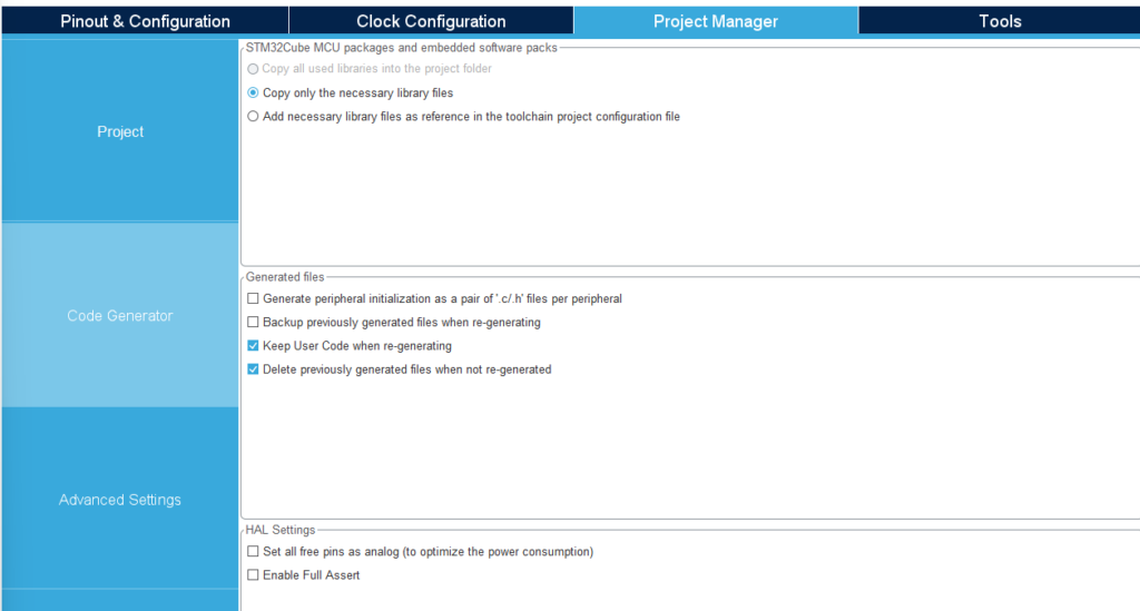
Click on Code Generator and ensure the following options are selected:
-
- STM32Cube MCU packages and embedded software packs > Copy only the necessary library files
- Generated files > Keep User Code when re-generating

Finally click on Generate Code followed by Open Project in the popup to open the project in STM32CubeIDE


Source Code Configuration with HAL
Now we need to add in the code changes that toggle the LED. To determine which functions to use, we need to look at the HAL User Manual for our STM32MCU. HAL or Hardware Abstraction Layer is the set of low level functions that we can use to control the STM32 MCU without needing to worry too much about what’s going on under the hood. The HAL User manual for the STM32F7 series is UM1905 and can be found here.
Inside the user manual we’ll find HAL_GPIO_TogglePin which toggles a GPIO pin from LOW to HIGH or HIGH to LOW depending on the state when it’s called.
In the Project Explorer sidebar open Src/main.c and navigate to the while(1) loop between the /* USER CODE BEGIN 3 */ and /* USER CODE END 3 */ section. Placing code in here will preserve it after regeneration with STM32CubeMX.
Add the following snippet inside the loop to toggle the LED and delay for 0.5 seconds so we can see it blink:
HAL_GPIO_TogglePin(GPIOB, GPIO_PIN_7);
HAL_Delay(500) /* 500 ms delay */
Build and Debug the Project
Ensure the CN1 connector if applicable on your board to allow the board to be powered over the USB connection
To build the project, either click the Build button in the toolbar OR right click on the project in the project explorer side base and select Build Project


To debug the project, click on the debug icon  and OK in the Edit Configuration popup

This should open the debugger. You can switch to the debugger view if desired but it’s not necessary. If you see Download verified successfully in the console your program has been successfully loaded onto the MCU!

Click on the Resume button to continue program execution

You should now see the Blue LED flashing. Congratulations! You are now able to:
-
- Graphically configure GPIO Pins with STM32CubeMX
- Add GPIO functionality in code with STM32CubeIDE
- Find and use HAL functions for cleaner and easier to write code
Great job! For more check out Lesson 3: USART

