Intro to STM32 Lesson 4: ADC/DMA
Time Required: 30 Minutes
This tutorial introduces the analog-to-digital converter (ADC) as well as the direct memory access (DMA) controller. While these two hardware peripherals don’t necessarily need to be used together they certainly can help each other!
Prerequisites Before Starting
-
- Everything from Lessons 1 through 3
- STM32 MCU of your choice with USB cable
ADC
MCUs are digital components and, as a result, can only process digital signals from GPIO pins. Of course, there are an infinite number of voltage levels between LOW (0V) and HIGH (3V3, 5V, etc.). Many types of signals such as audio are entirely analog. To capture these types of signals we use an ADC which samples the signal at a specified sampling rate. By taking a measurement at each sample time, we are able to approximate the analog signal digitally:

(Source: Tony R. Kuphaldt – Lessons in Electric Circuits)
As can be seen in the example above, a few samples will begin to approximate the signal but won’t entirely recreate it. When this loss of accuracy occurs during sampling it is called aliasing. In order to prevent aliasing we must sample at the Nyquist Frequency which is twice the maximum frequency within the signal.
Each ADC has a resolution, typically 10-bit or 12-bit:

As the ADC resolution increases, so does the resolution of the sampled digital signal:

(Source: Apple Inc – Soundtrack Pro 3: Audio Fundamentals)
There are two types of ADC implementations used with STM32 chips, each with advantages and disadvantages:
-
- Successive-Approximation Register (SAR)
- Faster, less resolution
- Sigma-Delta Modulation
-
- Slower, more resolution
-
- Successive-Approximation Register (SAR)
For the purposes of this tutorial we will be using a NUCLEO-144 with STM32F756ZG MCU. From the ST website we can tell that it is equipped with 3 x 12-bit ADCs.
DMA
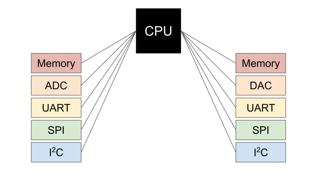
One of the biggest challenges with processing ADC data is the sheer amount of it. MCUs are relatively lightweight processors with limited memory and processing capabilities. If the CPU is occupied moving an ADC reading from the hardware buffer into memory it cannot be performing a calculation on the data at the same time. Every byte that needs to pass through the CPU slows it down, this is where DMA can make a world of difference.
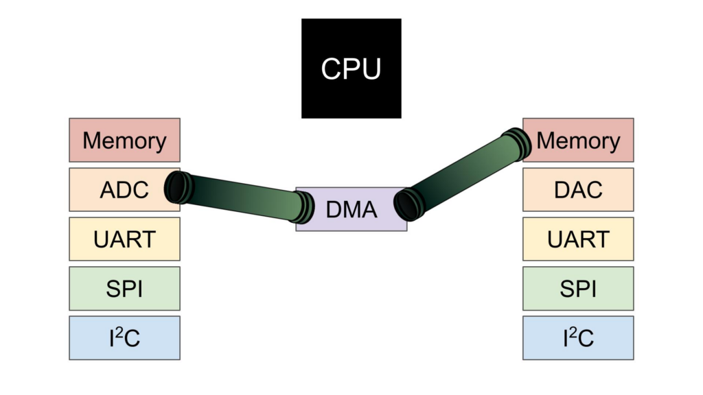
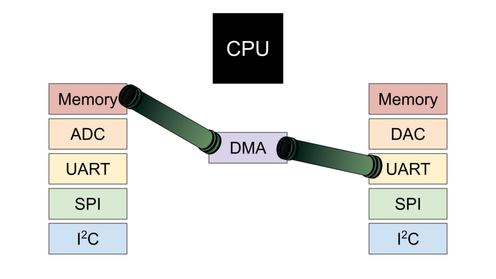
Most modern processors have a hardware DMA controller. There is a small amount of CPU time required to configure the peripheral, but in cases of large data transfers this initial cost is almost always eclipsed by the total time saved. DMA can be imagined as a temporary information highway that can be placed between two destinations in the MCU, such as the ADC and Memory.
Consider an example where we need to collect significant amounts of data from an ADC and store it in a Memory buffer. Without DMA, every time the ADC raises an interrupt to signal it has data ready to read the CPU needs to stop what it’s doing, read the data into a CPU register, then write it to the Memory buffer before it can resume what it was doing before. In this case the CPU becomes the bottleneck, restricting the system from operating at it’s maximum throughput due to constant context changes.
Adding a DMA pipeline transforms the system from this:
To this, effectively removing the CPU bottleneck:
Reading From the ADC
Let’s start with a simple ADC conversion, confirm everything is working properly, then add DMA. Configure USART3 as Asynchronous with PD9 as USART3_RX and PD8 as USART3_TX in the GUI:
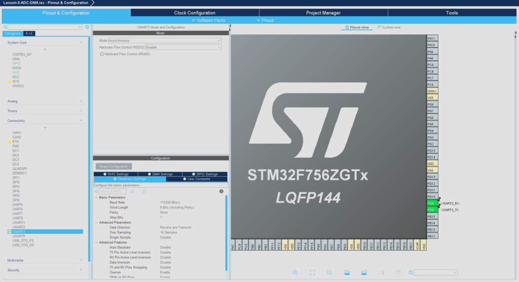
Note: Different pins will likely need to be selected for non-STM32F756ZG boards.
Enable IN0 for ADC1 and set PA0 as ADC1_IN0 :
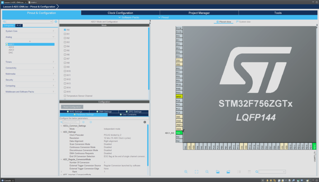
Note: Different pins will likely need to be selected for non-STM32F756ZG boards.
Add the following changes to main.c :
/* USER CODE BEGIN Header */
/**
  ******************************************************************************
  * @file           : main.c
  * @brief          : Main program body
  ******************************************************************************
  * @attention
  *
  * Copyright (c) 2024 STMicroelectronics.
  * All rights reserved.
  *
  * This software is licensed under terms that can be found in the LICENSE file
  * in the root directory of this software component.
  * If no LICENSE file comes with this software, it is provided AS-IS.
  *
  ******************************************************************************
  */
/* USER CODE END Header */
/* Includes ------------------------------------------------------------------*/
#include "main.h"

/* Private includes ----------------------------------------------------------*/
/* USER CODE BEGIN Includes */
#include <string.h>
#include <stdio.h>
/* USER CODE END Includes */

/* Private typedef -----------------------------------------------------------*/
/* USER CODE BEGIN PTD */

/* USER CODE END PTD */

/* Private define ------------------------------------------------------------*/
/* USER CODE BEGIN PD */

/* USER CODE END PD */

/* Private macro -------------------------------------------------------------*/
/* USER CODE BEGIN PM */

/* USER CODE END PM */

/* Private variables ---------------------------------------------------------*/
ADC_HandleTypeDef hadc1;

UART_HandleTypeDef huart3;

/* USER CODE BEGIN PV */

/* USER CODE END PV */

/* Private function prototypes -----------------------------------------------*/
void SystemClock_Config(void);
static void MX_GPIO_Init(void);
static void MX_ADC1_Init(void);
static void MX_USART3_UART_Init(void);
/* USER CODE BEGIN PFP */

/* USER CODE END PFP */

/* Private user code ---------------------------------------------------------*/
/* USER CODE BEGIN 0 */

/* USER CODE END 0 */

/**
  * @brief  The application entry point.
  * @retval int
  */
int main(void)
{
  /* USER CODE BEGIN 1 */
  uint16_t buffer;
  char msg[4];

  /* USER CODE END 1 */

  /* MCU Configuration--------------------------------------------------------*/

  /* Reset of all peripherals, Initializes the Flash interface and the Systick. */
  HAL_Init();

  /* USER CODE BEGIN Init */

  /* USER CODE END Init */

  /* Configure the system clock */
  SystemClock_Config();

  /* USER CODE BEGIN SysInit */

  /* USER CODE END SysInit */

  /* Initialize all configured peripherals */
  MX_GPIO_Init();
  MX_ADC1_Init();
  MX_USART3_UART_Init();
  /* USER CODE BEGIN 2 */

  /* USER CODE END 2 */

  /* Infinite loop */
  /* USER CODE BEGIN WHILE */
  while (1)
  {
    // Get ADC value
    HAL_ADC_Start(&hadc1);
    HAL_ADC_PollForConversion(&hadc1, HAL_MAX_DELAY);
    buffer = HAL_ADC_GetValue(&hadc1);

    // Convert to string and print
    sprintf(buffer, "%hurn", buffer);
    HAL_UART_Transmit(&huart3, (uint8_t*)buffer, strlen(buffer), HAL_MAX_DELAY);

    // Delay
    HAL_Delay(1);

    /* USER CODE END WHILE */

    /* USER CODE BEGIN 3 */
  }
  /* USER CODE END 3 */
}

/**
  * @brief System Clock Configuration
  * @retval None
  */
void SystemClock_Config(void)
{
  RCC_OscInitTypeDef RCC_OscInitStruct = {0};
  RCC_ClkInitTypeDef RCC_ClkInitStruct = {0};

  /** Configure the main internal regulator output voltage
  */
  __HAL_RCC_PWR_CLK_ENABLE();
  __HAL_PWR_VOLTAGESCALING_CONFIG(PWR_REGULATOR_VOLTAGE_SCALE3);

  /** Initializes the RCC Oscillators according to the specified parameters
  * in the RCC_OscInitTypeDef structure.
  */
  RCC_OscInitStruct.OscillatorType = RCC_OSCILLATORTYPE_HSI;
  RCC_OscInitStruct.HSIState = RCC_HSI_ON;
  RCC_OscInitStruct.HSICalibrationValue = RCC_HSICALIBRATION_DEFAULT;
  RCC_OscInitStruct.PLL.PLLState = RCC_PLL_NONE;
  if (HAL_RCC_OscConfig(&RCC_OscInitStruct) != HAL_OK)
  {
    Error_Handler();
  }

  /** Initializes the CPU, AHB and APB buses clocks
  */
  RCC_ClkInitStruct.ClockType = RCC_CLOCKTYPE_HCLK|RCC_CLOCKTYPE_SYSCLK
                              |RCC_CLOCKTYPE_PCLK1|RCC_CLOCKTYPE_PCLK2;
  RCC_ClkInitStruct.SYSCLKSource = RCC_SYSCLKSOURCE_HSI;
  RCC_ClkInitStruct.AHBCLKDivider = RCC_SYSCLK_DIV1;
  RCC_ClkInitStruct.APB1CLKDivider = RCC_HCLK_DIV1;
  RCC_ClkInitStruct.APB2CLKDivider = RCC_HCLK_DIV1;

  if (HAL_RCC_ClockConfig(&RCC_ClkInitStruct, FLASH_LATENCY_0) != HAL_OK)
  {
    Error_Handler();
  }
}

/**
  * @brief ADC1 Initialization Function
  * @param None
  * @retval None
  */
static void MX_ADC1_Init(void)
{

  /* USER CODE BEGIN ADC1_Init 0 */

  /* USER CODE END ADC1_Init 0 */

  ADC_ChannelConfTypeDef sConfig = {0};

  /* USER CODE BEGIN ADC1_Init 1 */

  /* USER CODE END ADC1_Init 1 */

  /** Configure the global features of the ADC (Clock, Resolution, Data Alignment and number of conversion)
  */
  hadc1.Instance = ADC1;
  hadc1.Init.ClockPrescaler = ADC_CLOCK_SYNC_PCLK_DIV2;
  hadc1.Init.Resolution = ADC_RESOLUTION_12B;
  hadc1.Init.ScanConvMode = ADC_SCAN_DISABLE;
  hadc1.Init.ContinuousConvMode = DISABLE;
  hadc1.Init.DiscontinuousConvMode = DISABLE;
  hadc1.Init.ExternalTrigConvEdge = ADC_EXTERNALTRIGCONVEDGE_NONE;
  hadc1.Init.ExternalTrigConv = ADC_SOFTWARE_START;
  hadc1.Init.DataAlign = ADC_DATAALIGN_RIGHT;
  hadc1.Init.NbrOfConversion = 1;
  hadc1.Init.DMAContinuousRequests = DISABLE;
  hadc1.Init.EOCSelection = ADC_EOC_SINGLE_CONV;
  if (HAL_ADC_Init(&hadc1) != HAL_OK)
  {
    Error_Handler();
  }

  /** Configure for the selected ADC regular channel its corresponding rank in the sequencer and its sample time.
  */
  sConfig.Channel = ADC_CHANNEL_0;
  sConfig.Rank = ADC_REGULAR_RANK_1;
  sConfig.SamplingTime = ADC_SAMPLETIME_3CYCLES;
  if (HAL_ADC_ConfigChannel(&hadc1, &sConfig) != HAL_OK)
  {
    Error_Handler();
  }
  /* USER CODE BEGIN ADC1_Init 2 */

  /* USER CODE END ADC1_Init 2 */

}

/**
  * @brief USART3 Initialization Function
  * @param None
  * @retval None
  */
static void MX_USART3_UART_Init(void)
{

  /* USER CODE BEGIN USART3_Init 0 */

  /* USER CODE END USART3_Init 0 */

  /* USER CODE BEGIN USART3_Init 1 */

  /* USER CODE END USART3_Init 1 */
  huart3.Instance = USART3;
  huart3.Init.BaudRate = 115200;
  huart3.Init.WordLength = UART_WORDLENGTH_8B;
  huart3.Init.StopBits = UART_STOPBITS_1;
  huart3.Init.Parity = UART_PARITY_NONE;
  huart3.Init.Mode = UART_MODE_TX_RX;
  huart3.Init.HwFlowCtl = UART_HWCONTROL_NONE;
  huart3.Init.OverSampling = UART_OVERSAMPLING_16;
  huart3.Init.OneBitSampling = UART_ONE_BIT_SAMPLE_DISABLE;
  huart3.AdvancedInit.AdvFeatureInit = UART_ADVFEATURE_NO_INIT;
  if (HAL_UART_Init(&huart3) != HAL_OK)
  {
    Error_Handler();
  }
  /* USER CODE BEGIN USART3_Init 2 */

  /* USER CODE END USART3_Init 2 */

}

/**
  * @brief GPIO Initialization Function
  * @param None
  * @retval None
  */
static void MX_GPIO_Init(void)
{
/* USER CODE BEGIN MX_GPIO_Init_1 */
/* USER CODE END MX_GPIO_Init_1 */

  /* GPIO Ports Clock Enable */
  __HAL_RCC_GPIOA_CLK_ENABLE();
  __HAL_RCC_GPIOD_CLK_ENABLE();

/* USER CODE BEGIN MX_GPIO_Init_2 */
/* USER CODE END MX_GPIO_Init_2 */
}

/* USER CODE BEGIN 4 */

/* USER CODE END 4 */

/**
  * @brief  This function is executed in case of error occurrence.
  * @retval None
  */
void Error_Handler(void)
{
  /* USER CODE BEGIN Error_Handler_Debug */
  /* User can add his own implementation to report the HAL error return state */
  __disable_irq();
  while (1)
  {
  }
  /* USER CODE END Error_Handler_Debug */
}

#ifdef  USE_FULL_ASSERT
/**
  * @brief  Reports the name of the source file and the source line number
  *         where the assert_param error has occurred.
  * @param  file: pointer to the source file name
  * @param  line: assert_param error line source number
  * @retval None
  */
void assert_failed(uint8_t *file, uint32_t line)
{
  /* USER CODE BEGIN 6 */
  /* User can add his own implementation to report the file name and line number,
     ex: printf("Wrong parameters value: file %s on line %drn", file, line) */
  /* USER CODE END 6 */
}
#endif /* USE_FULL_ASSERT */
Press Run and open a PuTTY terminal or other serial console of your choice. Set the baud rate to 115200 and ensure the correct COM port is selected, then open the connection. There should be a stream of numbers displayed within the ADC value range (in this case 0 to 4095) if the pin was left floating (not connected):

Piping ADC Readings to USART With DMA
For this example, we will be using DMA to directly transfer a buffer of ADC readings byte-by-byte over USART with minimal CPU usage. DMA can help us easily transfer data from one hardware peripheral to another. Consider this diagram with a slight variation from the one above:
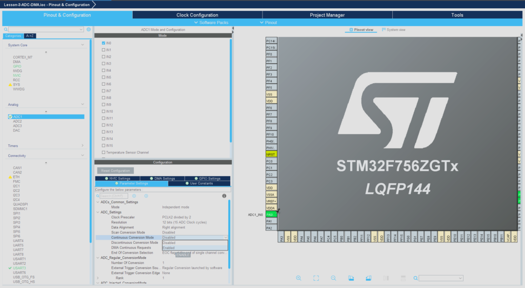
First, set ADC1 > Parameter Settings > Continuous Conversion Mode to Enabled.
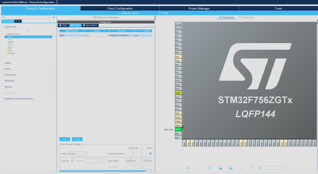
Now we need to assign the DMA request so the ADC pin can be set to DMA mode. Go to DMA > DMA2 > Add New Request and set it to ADC1. Note: You may need to use DMA1 or vice versa depending on your MCU. Change the mode to circular so the DMA will utilize a circular buffer and wrap around to the top of the buffer once it’s been filled up.
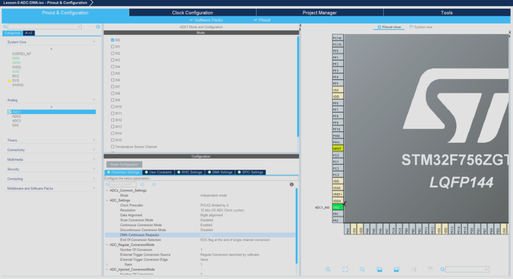
Go back to the ADC1 settings and set DMA Continuous Requests to Enabled:
Add the following changes to main.c
/* USER CODE BEGIN Header */
/**
  ******************************************************************************
  * @file           : main.c
  * @brief          : Main program body
  ******************************************************************************
  * @attention
  *
  * Copyright (c) 2024 STMicroelectronics.
  * All rights reserved.
  *
  * This software is licensed under terms that can be found in the LICENSE file
  * in the root directory of this software component.
  * If no LICENSE file comes with this software, it is provided AS-IS.
  *
  ******************************************************************************
  */
/* USER CODE END Header */
/* Includes ------------------------------------------------------------------*/
#include "main.h"

/* Private includes ----------------------------------------------------------*/
/* USER CODE BEGIN Includes */
#include <string.h>
#include <stdio.h>
/* USER CODE END Includes */

/* Private typedef -----------------------------------------------------------*/
/* USER CODE BEGIN PTD */

/* USER CODE END PTD */

/* Private define ------------------------------------------------------------*/
/* USER CODE BEGIN PD */
#define ADC_BUF_LEN 2048
/* USER CODE END PD */

/* Private macro -------------------------------------------------------------*/
/* USER CODE BEGIN PM */

/* USER CODE END PM */

/* Private variables ---------------------------------------------------------*/
ADC_HandleTypeDef hadc1;
DMA_HandleTypeDef hdma_adc1;

UART_HandleTypeDef huart3;

/* USER CODE BEGIN PV */
uint16_t adc_buf[ADC_BUF_LEN];
/* USER CODE END PV */

/* Private function prototypes -----------------------------------------------*/
void SystemClock_Config(void);
static void MX_GPIO_Init(void);
static void MX_DMA_Init(void);
static void MX_ADC1_Init(void);
static void MX_USART3_UART_Init(void);
/* USER CODE BEGIN PFP */

/* USER CODE END PFP */

/* Private user code ---------------------------------------------------------*/
/* USER CODE BEGIN 0 */

/* USER CODE END 0 */

/**
  * @brief  The application entry point.
  * @retval int
  */
int main(void)
{
  /* USER CODE BEGIN 1 */
  uint16_t buffer;
  char msg[4];

  /* USER CODE END 1 */

  /* MCU Configuration--------------------------------------------------------*/

  /* Reset of all peripherals, Initializes the Flash interface and the Systick. */
  HAL_Init();

  /* USER CODE BEGIN Init */

  /* USER CODE END Init */

  /* Configure the system clock */
  SystemClock_Config();

  /* USER CODE BEGIN SysInit */

  /* USER CODE END SysInit */

  /* Initialize all configured peripherals */
  MX_GPIO_Init();
  MX_DMA_Init();
  MX_ADC1_Init();
  MX_USART3_UART_Init();
  /* USER CODE BEGIN 2 */
  HAL_ADC_Start_DMA(&hadc1, (uint32_t*)adc_buf, ADC_BUF_LEN);
  /* USER CODE END 2 */

  /* Infinite loop */
  /* USER CODE BEGIN WHILE */
  while (1)
  {
    // Get ADC value
    HAL_ADC_Start(&hadc1);
    HAL_ADC_PollForConversion(&hadc1, HAL_MAX_DELAY);
    buffer = HAL_ADC_GetValue(&hadc1);

    // Convert to string and print
    sprintf(buffer, "%hurn", buffer);
    HAL_UART_Transmit(&huart3, (uint8_t*)buffer, strlen(buffer), HAL_MAX_DELAY);

    // Delay
    HAL_Delay(1);

    /* USER CODE END WHILE */

    /* USER CODE BEGIN 3 */
  }
  /* USER CODE END 3 */
}

/**
  * @brief System Clock Configuration
  * @retval None
  */
void SystemClock_Config(void)
{
  RCC_OscInitTypeDef RCC_OscInitStruct = {0};
  RCC_ClkInitTypeDef RCC_ClkInitStruct = {0};

  /** Configure the main internal regulator output voltage
  */
  __HAL_RCC_PWR_CLK_ENABLE();
  __HAL_PWR_VOLTAGESCALING_CONFIG(PWR_REGULATOR_VOLTAGE_SCALE3);

  /** Initializes the RCC Oscillators according to the specified parameters
  * in the RCC_OscInitTypeDef structure.
  */
  RCC_OscInitStruct.OscillatorType = RCC_OSCILLATORTYPE_HSI;
  RCC_OscInitStruct.HSIState = RCC_HSI_ON;
  RCC_OscInitStruct.HSICalibrationValue = RCC_HSICALIBRATION_DEFAULT;
  RCC_OscInitStruct.PLL.PLLState = RCC_PLL_NONE;
  if (HAL_RCC_OscConfig(&RCC_OscInitStruct) != HAL_OK)
  {
    Error_Handler();
  }

  /** Initializes the CPU, AHB and APB buses clocks
  */
  RCC_ClkInitStruct.ClockType = RCC_CLOCKTYPE_HCLK|RCC_CLOCKTYPE_SYSCLK
                              |RCC_CLOCKTYPE_PCLK1|RCC_CLOCKTYPE_PCLK2;
  RCC_ClkInitStruct.SYSCLKSource = RCC_SYSCLKSOURCE_HSI;
  RCC_ClkInitStruct.AHBCLKDivider = RCC_SYSCLK_DIV1;
  RCC_ClkInitStruct.APB1CLKDivider = RCC_HCLK_DIV1;
  RCC_ClkInitStruct.APB2CLKDivider = RCC_HCLK_DIV1;

  if (HAL_RCC_ClockConfig(&RCC_ClkInitStruct, FLASH_LATENCY_0) != HAL_OK)
  {
    Error_Handler();
  }
}

/**
  * @brief ADC1 Initialization Function
  * @param None
  * @retval None
  */
static void MX_ADC1_Init(void)
{

  /* USER CODE BEGIN ADC1_Init 0 */

  /* USER CODE END ADC1_Init 0 */

  ADC_ChannelConfTypeDef sConfig = {0};

  /* USER CODE BEGIN ADC1_Init 1 */

  /* USER CODE END ADC1_Init 1 */

  /** Configure the global features of the ADC (Clock, Resolution, Data Alignment and number of conversion)
  */
  hadc1.Instance = ADC1;
  hadc1.Init.ClockPrescaler = ADC_CLOCK_SYNC_PCLK_DIV2;
  hadc1.Init.Resolution = ADC_RESOLUTION_12B;
  hadc1.Init.ScanConvMode = ADC_SCAN_DISABLE;
  hadc1.Init.ContinuousConvMode = ENABLE;
  hadc1.Init.DiscontinuousConvMode = DISABLE;
  hadc1.Init.ExternalTrigConvEdge = ADC_EXTERNALTRIGCONVEDGE_NONE;
  hadc1.Init.ExternalTrigConv = ADC_SOFTWARE_START;
  hadc1.Init.DataAlign = ADC_DATAALIGN_RIGHT;
  hadc1.Init.NbrOfConversion = 1;
  hadc1.Init.DMAContinuousRequests = ENABLE;
  hadc1.Init.EOCSelection = ADC_EOC_SINGLE_CONV;
  if (HAL_ADC_Init(&hadc1) != HAL_OK)
  {
    Error_Handler();
  }

  /** Configure for the selected ADC regular channel its corresponding rank in the sequencer and its sample time.
  */
  sConfig.Channel = ADC_CHANNEL_0;
  sConfig.Rank = ADC_REGULAR_RANK_1;
  sConfig.SamplingTime = ADC_SAMPLETIME_3CYCLES;
  if (HAL_ADC_ConfigChannel(&hadc1, &sConfig) != HAL_OK)
  {
    Error_Handler();
  }
  /* USER CODE BEGIN ADC1_Init 2 */

  /* USER CODE END ADC1_Init 2 */

}

/**
  * @brief USART3 Initialization Function
  * @param None
  * @retval None
  */
static void MX_USART3_UART_Init(void)
{

  /* USER CODE BEGIN USART3_Init 0 */

  /* USER CODE END USART3_Init 0 */

  /* USER CODE BEGIN USART3_Init 1 */

  /* USER CODE END USART3_Init 1 */
  huart3.Instance = USART3;
  huart3.Init.BaudRate = 115200;
  huart3.Init.WordLength = UART_WORDLENGTH_8B;
  huart3.Init.StopBits = UART_STOPBITS_1;
  huart3.Init.Parity = UART_PARITY_NONE;
  huart3.Init.Mode = UART_MODE_TX_RX;
  huart3.Init.HwFlowCtl = UART_HWCONTROL_NONE;
  huart3.Init.OverSampling = UART_OVERSAMPLING_16;
  huart3.Init.OneBitSampling = UART_ONE_BIT_SAMPLE_DISABLE;
  huart3.AdvancedInit.AdvFeatureInit = UART_ADVFEATURE_NO_INIT;
  if (HAL_UART_Init(&huart3) != HAL_OK)
  {
    Error_Handler();
  }
  /* USER CODE BEGIN USART3_Init 2 */

  /* USER CODE END USART3_Init 2 */

}

/**
  * Enable DMA controller clock
  */
static void MX_DMA_Init(void)
{

  /* DMA controller clock enable */
  __HAL_RCC_DMA2_CLK_ENABLE();

  /* DMA interrupt init */
  /* DMA2_Stream0_IRQn interrupt configuration */
  HAL_NVIC_SetPriority(DMA2_Stream0_IRQn, 0, 0);
  HAL_NVIC_EnableIRQ(DMA2_Stream0_IRQn);

}

/**
  * @brief GPIO Initialization Function
  * @param None
  * @retval None
  */
static void MX_GPIO_Init(void)
{
/* USER CODE BEGIN MX_GPIO_Init_1 */
/* USER CODE END MX_GPIO_Init_1 */

  /* GPIO Ports Clock Enable */
  __HAL_RCC_GPIOA_CLK_ENABLE();
  __HAL_RCC_GPIOD_CLK_ENABLE();

/* USER CODE BEGIN MX_GPIO_Init_2 */
/* USER CODE END MX_GPIO_Init_2 */
}

/* USER CODE BEGIN 4 */

/* USER CODE END 4 */

/**
  * @brief  This function is executed in case of error occurrence.
  * @retval None
  */
void Error_Handler(void)
{
  /* USER CODE BEGIN Error_Handler_Debug */
  /* User can add his own implementation to report the HAL error return state */
  __disable_irq();
  while (1)
  {
  }
  /* USER CODE END Error_Handler_Debug */
}

#ifdef  USE_FULL_ASSERT
/**
  * @brief  Reports the name of the source file and the source line number
  *         where the assert_param error has occurred.
  * @param  file: pointer to the source file name
  * @param  line: assert_param error line source number
  * @retval None
  */
void assert_failed(uint8_t *file, uint32_t line)
{
  /* USER CODE BEGIN 6 */
  /* User can add his own implementation to report the file name and line number,
     ex: printf("Wrong parameters value: file %s on line %drn", file, line) */
  /* USER CODE END 6 */
}
#endif /* USE_FULL_ASSERT */
Press Run in STM32CubeIDE, then open up PuTTY. There should be a stream of numbers displayed within the ADC value range (in this case 0 to 4095) if the pin was left floating (not connected):

Congratulations! You can now read analog values with your STM32MCU without bottlenecking the CPU! Next we’ll dive into creating analog output values with a Digital to Analog Converter (DAC) and Pulse Width Modulation (PWM) in Lesson 5: DAC/PWM (coming soon).

