
Time Required: 20 Minutes

This tutorial goes through the steps for establishing a RS232 serial connection with an STM32 MCU for receiving and sending text over the USART or UART (Universal Synchronous Asynchronous Receiver Transmitter). Serial communication is the process of sequentially sending data one bit at a time over a single wire. It is one of the most simple yet effective methods of connecting your MCU with sensors, other processors, or, in this case, your computer.
Prerequisites Before Starting
- Everything from Lesson 2: GPIO
- STM32 Board
- Tutorial uses STM32F756ZG Nucleo 144
- USB Cable
Create a New Project with STM32XCubeMX
- Open STM32CubeMX
- Select New Project or Menu > File > New Project
- Under Board Selector select the series and type of your STM32 board, for this tutorial the NUCLEO-FZ576ZG STM32F7 Series Nucleo144 type will be used
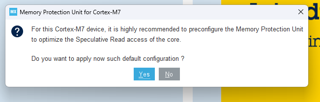
- Select Start Project and Yes for initializing all peripherals with their default mode including the MPU
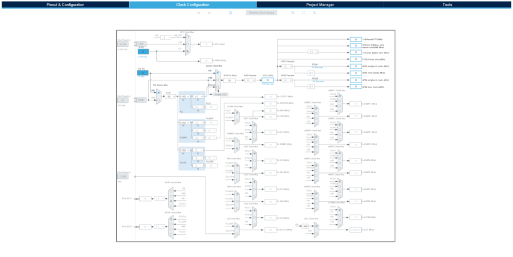
Clock Configuration
The default settings under Clock Configuration (see below) should be sufficient for the purpose of this application.
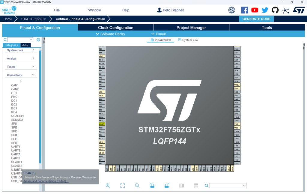
Pinout Configuration
STM32 Nucleo boards include an ST-LINK onboard USB programmer and debugger with a few extra features including a USART.
Many of the STM32 Software Defaults do not match the STM32 hardware defaults. Using your STM32’s datasheet and User Guide will be key to determining the correct pinout.
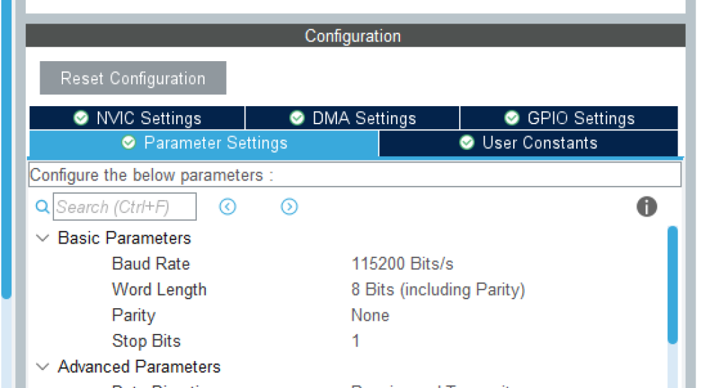
- Open Pinout & Configuration > Connectivity in STM32CubeMX and select USART3
- Under Mode select Asynchronous
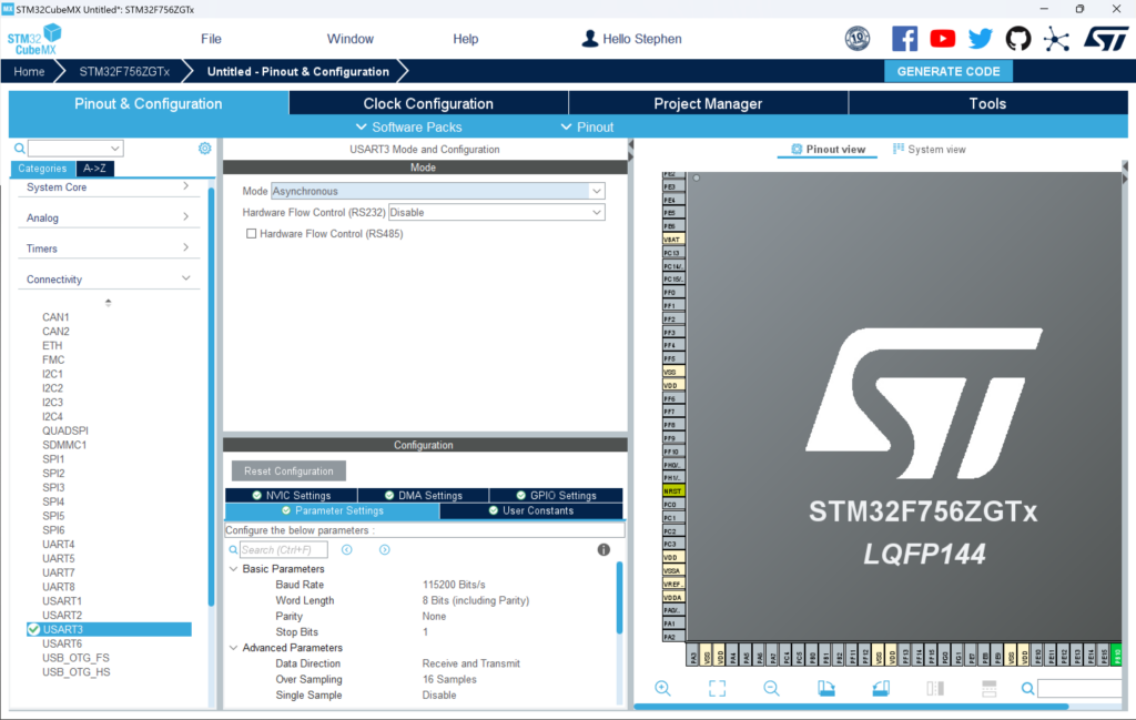
- Take note of the settings under Basic Parameters at the bottom as we’ll need these for our terminal later
- In the search bar, type
USART3_RX— you’ll see both PB11 and PD9 start blinking
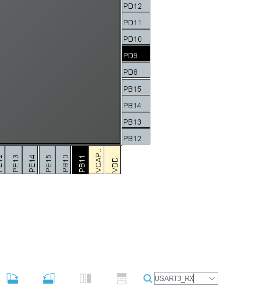
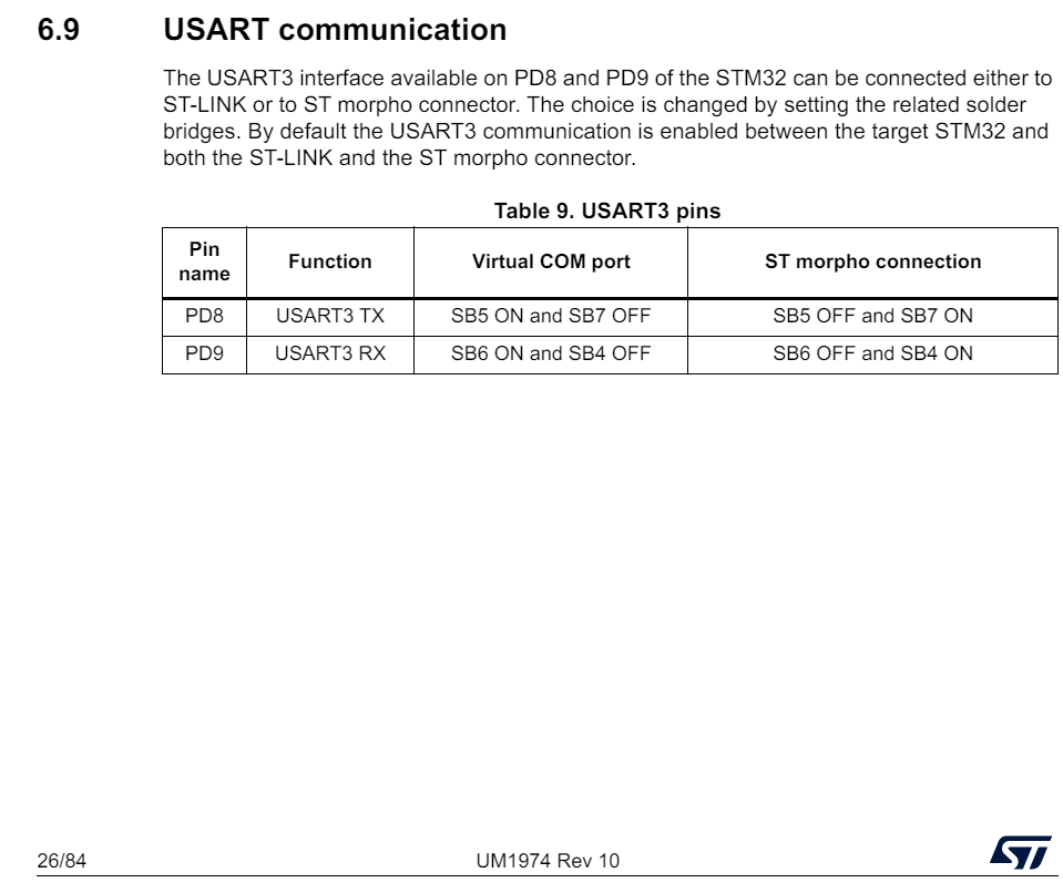
- Which pin is correct? Consult the Nucleo-144 User Manual section on USART communication. The table confirms: PD9 → USART3_RX and PD8 → USART3_TX
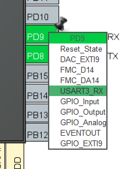
- Click on PD9 and select
USART3_RX. Click on PD8 and selectUSART3_TX
- Switch to the Project Manager tab, name the project, and select STM32CubeIDE as the Toolchain / IDE
- Now generate your code! If you need help doing this check out Lesson 2: GPIO
Code Configuration
- Open STM32CubeIDE
- Open
<YOUR_PROJECT_NAME>/Src/main.cin Project Explorer - Add the following snippet between
/* USER CODE BEGIN 3 */and/* USER CODE END 3 */
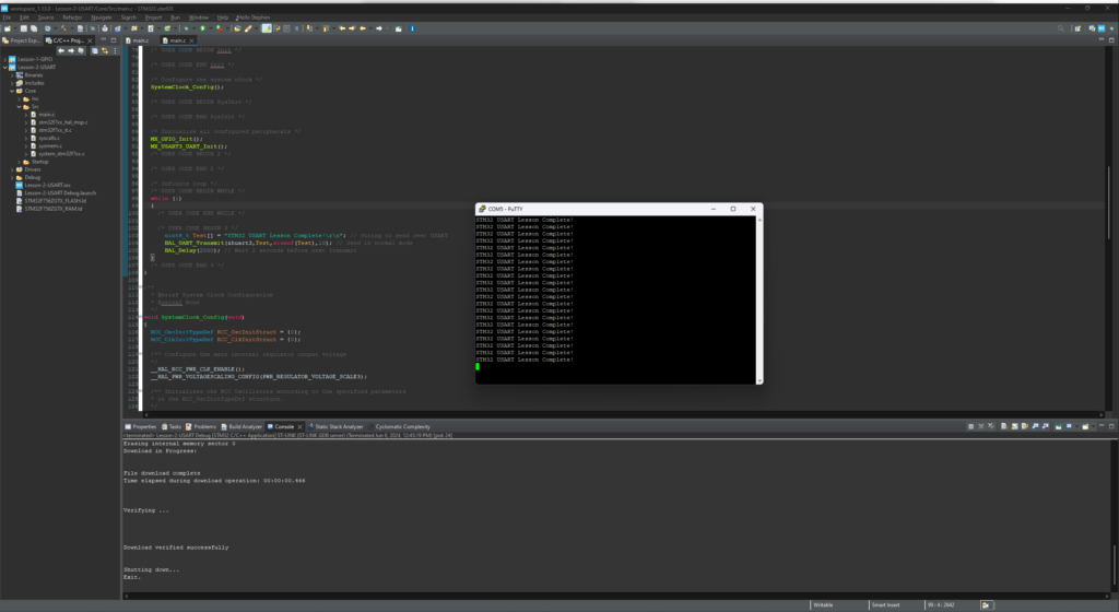
uint8_t Test[] = "STM32 USART Lesson Complete!\r\n"; // String to send over USART HAL_UART_Transmit(&huart3,Test,sizeof(Test),10); // Send in normal mode HAL_Delay(2000); // Wait 2 seconds before next transmit - Open a serial console emulator such as PuTTY or TeraTerm
- Set the baud rate and data bits to match the settings above: 115200 Baud, 8 Bit Data. Select the correct COM Port and open the connection
- In STM32CubeIDE click Run to build and load the project onto the STM32 MCU
STM32 USART Lesson Complete!should now be visible within your serial console
Congratulations! You can now communicate with your STM32MCU! Next we’ll dive into reading analog values with an Analog Digital Converter (ADC) and how to speed up this process with a Direct Memory Access (DMA) Controller in Lesson 4: ADC & DMA