
Time Required: 30 Minutes

This tutorial introduces the digital-to-analog converter (DAC) and Pulse Width Modulation (PWM). These two methods will allow us to create or approximate analog output from our digital MCU!
Prerequisites Before Starting
-
- Everything from Lessons 1 through 4
- STM32 MCU of your choice with USB cable
- Digital Multimeter and/ or Oscilloscope to measure output
DAC
MCUs are digital components and, as a result, are only capable of natively outputting a digital LOW (0V) or HIGH (3V3, 5V, etc.). A digital-to-analog (DAC) converter is a physical hardware system that converts a digitally configured register value into a corresponding analog output voltage.
Each DAC has a resolution, typically 10-bit or 12-bit:
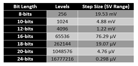
As the DAC resolution increases, so does the resolution of the output analog signal:
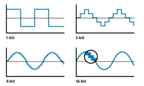
(Source: Apple Inc – Soundtrack Pro 3: Audio Fundamentals)
Some DACs also provide a Sample and Hold circuit to keep the output voltage steady between samples. The circuit samples the output voltage at discrete points in time and holds it at each sampled point until the next one is available to prevent fluctuations. There are two types of DAC system implementations:
- R-2R Ladder
- This implementation uses a network of resistors with values R and 2R to create the analog output.
- The DAC configuration register value determines which resistors are in the output signal path.
- This essentially generates a weighted sum of voltages corresponding to the desired analog output.
- As the precision and output resolution increases, so does the number of resistors and switches required.
- This implementation is typically used in embedded applications.
- Current-Steering (Delta-Sigma)
- This implementation first converts the digital input into a high-frequency pulse-density modulated (PDM) signal.
- The signal is then filtered through a low-pass filter to produce a smooth analog output signal.
- This implementation is typically used in high-quality audio systems as higher precision can be achieved with fewer physical components than R-2R DACs.
The STM32F756ZG has two 12-bit resolution R-2R DACs with the following features:
- Sample and Hold mode for reduced power consumption
- DMA capability with multiple triggers to offload CPU
- Low impedance buffered output to drive external circuits directly
- 8-bit or 12-bit mode with three supported input formats
Configuring DAC in STM32CubeIDE
Create a new project in STM32CubeIDE under File > New > STM32 Project. Select your board in the Board selector and download the library if you have not already. This course uses the STM32F756ZG with the STM32F756ZGT6 library. After, select a name for your project and confirm with the default options.
Open <PROJECT_NAME>.ioc and search for DAC in the left search field, then select OUT2 Configuration. The DAC is routed to PA5, which should now be highlighted green in the pinout view.
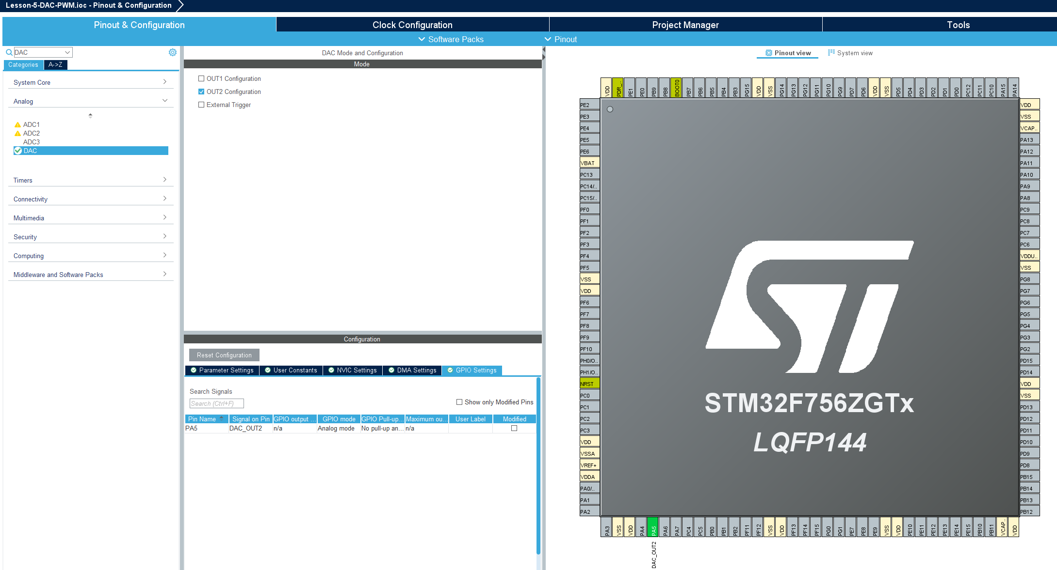
For our purposes the default settings are acceptable. Save the file and click Yes when prompted to generate code.
Note: If desired PA5 can be routed to the green user LED for testing by connecting solder bridge 119 (SB119) and disconnecting solder bridge 120 (SB120) on the rear side of the Nucleo-144.
To test our DAC configuration, let’s add some code to gradually output a higher analog voltage until we hit the limit of 3V, then reset back to 0V. This is also known as a Sawtooth Wave.
Add the following changes to <PROJECT_NAME>/Core/Src/main.c:
/* USER CODE BEGIN PV */
uint16_t dac_value=0;
/* USER CODE END PV */
...
/* USER CODE BEGIN 2 */
HAL_DAC_Start(&hdac, DAC_CHANNEL_2);
/* USER CODE END 2 */
...
/* USER CODE BEGIN 3 */
HAL_DAC_SetValue(&hdac, DAC_CHANNEL_2, DAC_ALIGN_12B_R, dac_value);
if (dac_value < 4095) {
	dac_value++;
} else {
	dac_value=0;
}
HAL_Delay(1);
/* USER CODE END 3 */
Then click Run  to load and execute the program.
Connect your oscilloscope to PA5 and start a capture to see the Sawtooth Wave.
PWM
Where the DAC produces a true analog voltage through dedicated hardware, Pulse Width Modulation (PWM) approximates an analog output by rapidly toggling a digital pin between LOW (0V) and HIGH (3V3, 5V, etc.) at a fixed frequency. The average voltage seen by a slow-responding load is determined by the ratio of time the signal spends HIGH versus LOW within each cycle, known as the duty cycle.
Each PWM signal is defined by three key parameters:
- Frequency: The number of full HIGH/LOW cycles per second, set by the timer’s clock source, prescaler, and auto-reload register (ARR).
- Duty Cycle: The percentage of each period that the signal is HIGH. A 25% duty cycle on a 3V3 line averages 0.825V, a 50% duty cycle averages 1.65V, and so on.
- Resolution: The number of discrete duty cycle steps available within one period, determined by the size of the ARR. A larger ARR provides finer duty cycle granularity at the cost of a lower maximum frequency.
(Source: TODO)
PWM is typically generated by a hardware timer counting up to a configured period, then comparing its count against a capture/compare register. When the count is below the compare value the output is driven one way; when above, the opposite. STM32 timers expose this behavior through two PWM output modes:
PWM Mode 1
- Output is HIGH while the timer count is less than the compare value, and LOW otherwise.
- This is the standard mode for most applications.
PWM Mode 2
- Output is LOW while the timer count is less than the compare value, and HIGH otherwise.
- Useful for inverted-logic loads or complementary output schemes.
PWM signals can also be edge-aligned or center-aligned. Edge-aligned PWM is the default and the simplest to configure. Center-aligned PWM is symmetric about the timer’s midpoint and reduces harmonic content for motor control applications.
The STM32F756ZG has 14 timers with PWM capability and the following features:
- TIM1 and TIM8 advanced-control timers with up to 4 PWM channels each, plus complementary outputs and dead-time insertion (ideal for motor control)
- TIM2 through TIM5 general-purpose 32-bit timers with up to 4 PWM channels each
- TIM9 through TIM14 general-purpose 16-bit timers with 1 to 2 PWM channels each
- Up to 216 MHz timer clock for high-resolution PWM generation
- DMA capability to offload repetitive duty cycle updates from the CPU
Configuring PWM in STM32CubeIDE
Open <PROJECT_NAME>.ioc and search for TIM3 in the left search field. Under Mode, set Clock Source to “Internal Clock” and set Channel1 to “PWM Generation CH1”. TIM3_CH1 is routed to PA6, which should now be highlighted green in the pinout view.
In the Parameter Settings tab below, configure the following values to generate a 1 kHz PWM signal:
- Prescaler: 107 (gives a 1 MHz timer tick from the 108 MHz APB1 timer clock)
- Counter Period (ARR): 999 (gives 1000 ticks per cycle, producing a 1 kHz output)
- PWM Mode: PWM mode 1
- Pulse: 0 (initial duty cycle of 0%)
Save the file and click Yes when prompted to generate code.
Note: TIM3_CH1 can also be routed to PB4 or PC6 if PA6 is needed for another peripheral.
To test our PWM configuration, let’s add some code to gradually increase the duty cycle from 0% to 100%, then reset back to 0%. This mirrors the DAC sawtooth in PWM form.
Add the following changes to <PROJECT_NAME>/Core/Src/main.c:
/* USER CODE BEGIN PV */
uint16_t pwm_value=0;
/ USER CODE END PV */
…
/* USER CODE BEGIN 2 /
HAL_TIM_PWM_Start(&htim3, TIM_CHANNEL_1);
/ USER CODE END 2 */
…
/* USER CODE BEGIN 3 /
__HAL_TIM_SET_COMPARE(&htim3, TIM_CHANNEL_1, pwm_value);
if (pwm_value < 1000) {
pwm_value++;
} else {
pwm_value=0;
}
HAL_Delay(1);
/ USER CODE END 3 */
Then click Run ![]() to load and execute the program.
to load and execute the program.
Connect your oscilloscope to PA6 and start a capture. As the duty cycle ramps, the HIGH time of each pulse should grow until the signal is fully HIGH, then snap back to a continuous LOW. If you place a simple RC low-pass filter (e.g. 1 kΩ resistor and 1 µF capacitor) between PA6 and your scope probe, you should see the same sawtooth waveform observed from the DAC, confirming that PWM, once smoothed by a slow-responding load, behaves like an analog output.